


 Direct purchase from the factory

![[US DIRECT] ATOMSTACK A5 M50 APP Control Dual-Laser Laser Engraving Cutting Machine Laser Engraver Cutter 5.5W Output Power Fixed-Focus 304 Mirror Stainless Steel Engraving DIY Laser Marking for Metal Wood Leather Vinyl](https://static.roymall.com/d/file/mall/titlepic/235/67803406-41f3-499a-afb7-154990584ff8.jpg?x-oss-process=image/resize,w_237/quality,Q_80/format,webp)
![[EU/US Direct]Raiser for LONGER RAY5 Engraver](https://static.roymall.com/d/file/mall/bigpic/235/65e9b76d-574a-4b4b-9c6c-02db18b89460.jpg?x-oss-process=image/resize,w_237/quality,Q_80/format,webp)
![[US/UK Direct] Refurbished ULTIMEA Nova S70 3.1.2 Soundbar 390W True Dolby Atmos Soundbar BassMax 4K Dolby Vision HDR Passthrough 3EQ Modes Wired Speaker Subwoofer](https://static.roymall.com/d/file/mall/titlepic/235/e1440062-c78c-4565-8aa7-f8857d749771.jpg?x-oss-process=image/resize,w_237/quality,Q_80/format,webp)


1.You can contact the customer service. for any question regarding the product.
2.Ask the question in English to get answer faster.
3.Keep your question short and to the point.
Questions:0/2000

 Multi Rotor PartsFPV SystemRadios & ReceiverBattery & ChargerTools & Bags & StorageConnector & Cable & WireRC ServosElectronic Learning ToysPlane & Parachute ToysSolar Powered ToysPottery Clay & ToolsPaper Art & DrawingBlocks & Track ToysModel BuildingDiecasts & Model ToysProtective GearsMotorcycle LightsCharger & Socket AdapterMotorcycle Engines & ComponentMotorcycle HelmetMotorcycle DIY KitsMotorcycle AccessoriesMotorcycle Alarm & SecurityCar Stickers & DecalsCar CoversWindow FoilsCar Protective FilmCar Protective Film Body ArmorLicense Plate AccessoriesDIY Electronic KitsElectronic Accessories & SuppliesModule ComponentsBoard & ShieldExpansion Board & ShieldSmart ModuleSensor & Detector ModulePower Supply ModuleRaspberry Pi & Orange PiSecurity Alarm SystemSmart Remote ControlWeather Station & ThermometerAccess Control & IntercomsHome Automatic KitsAutomation ModulesClocksHome Decor StickerDecorative PaintingDecorative CraftsStorage BagsStorage BoxesItems Storage & OrganizationSeedsWatering & IrrigationGarden LightsPest Control ProductsBathroom ApplianceShowerhead & AccessoriesBathroom Storage & OrganisationBathroom SafetyDoor Hardware & LocksIndustrial HardwareDecorative HardwarePackaging & ShippingStorage & OrganizationFurniture HardwareKitchen Tools & GadgetsDrinkware & Tea SetsBakeware & AccessoriesHome Brewing & Wine MakingKitchen Knife & CutleryBarbecue & Picnic SuppliesDinnerware & FlatwareXiaomi Kitchen Appliance
Guaranteed Safe Checkout

 Free Gift
 Shipping Policy
 Return Policy
A part of the review has been auto-translated.
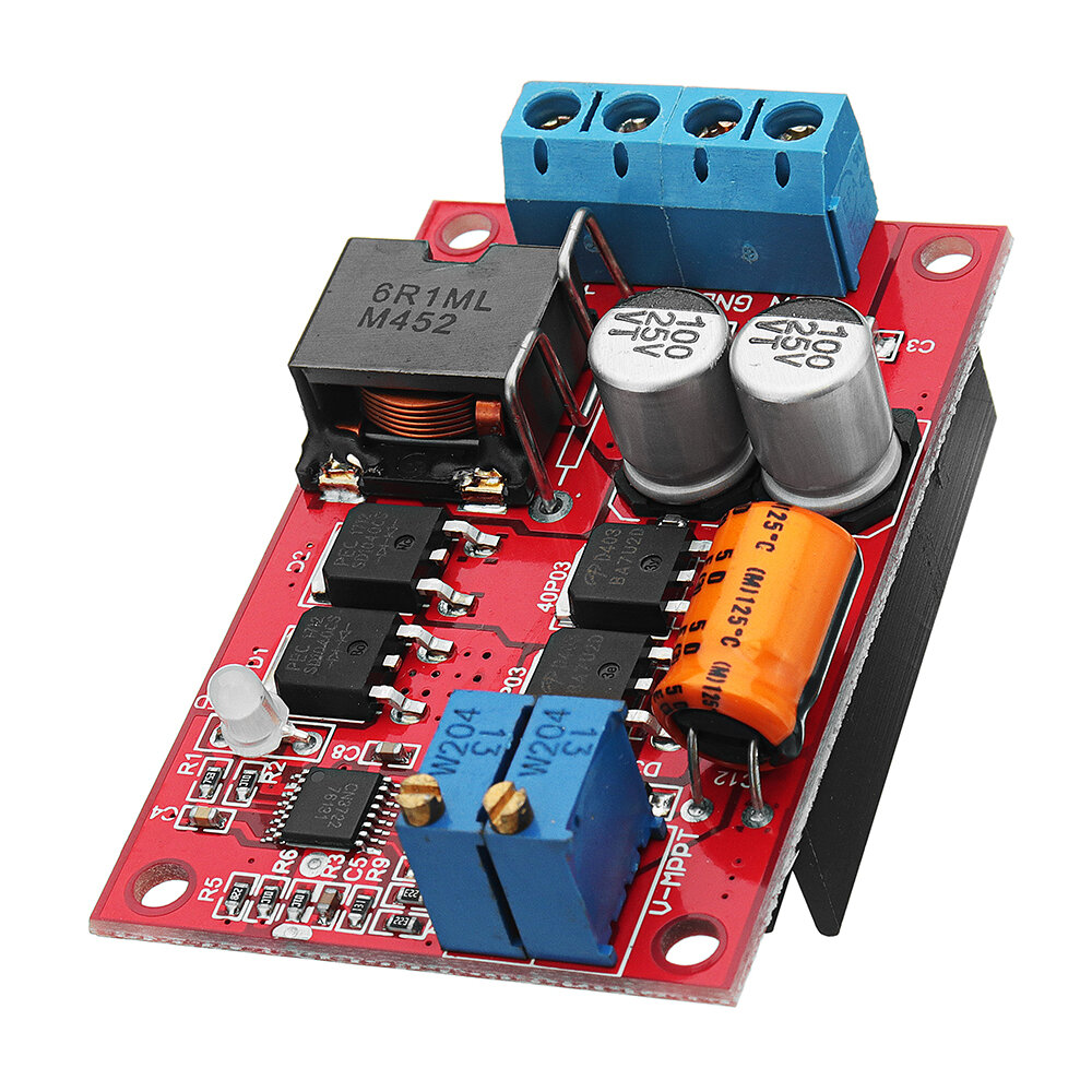
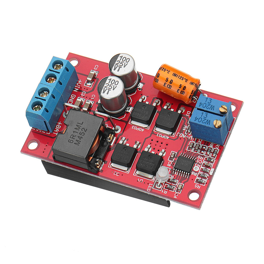
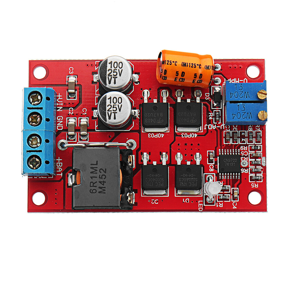
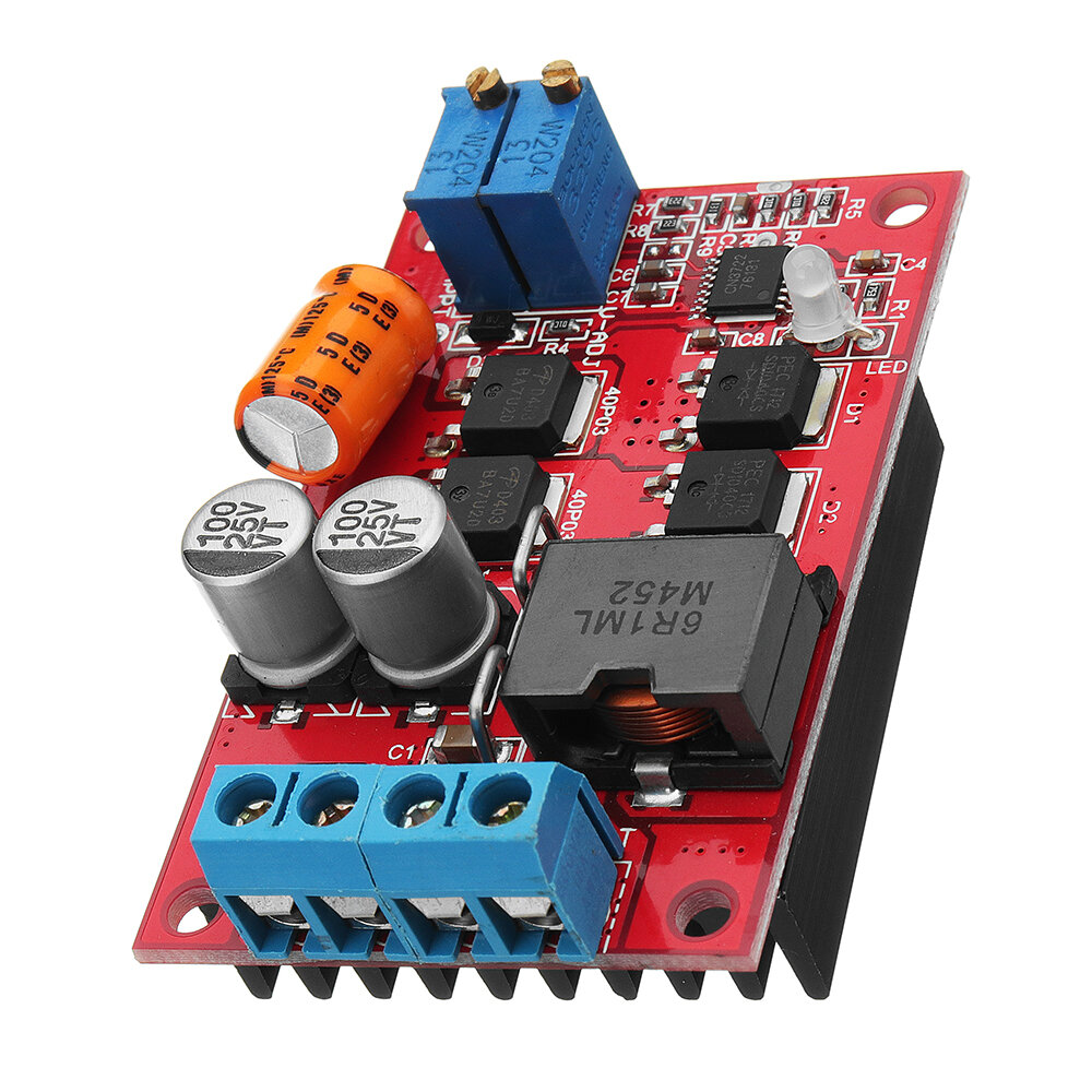
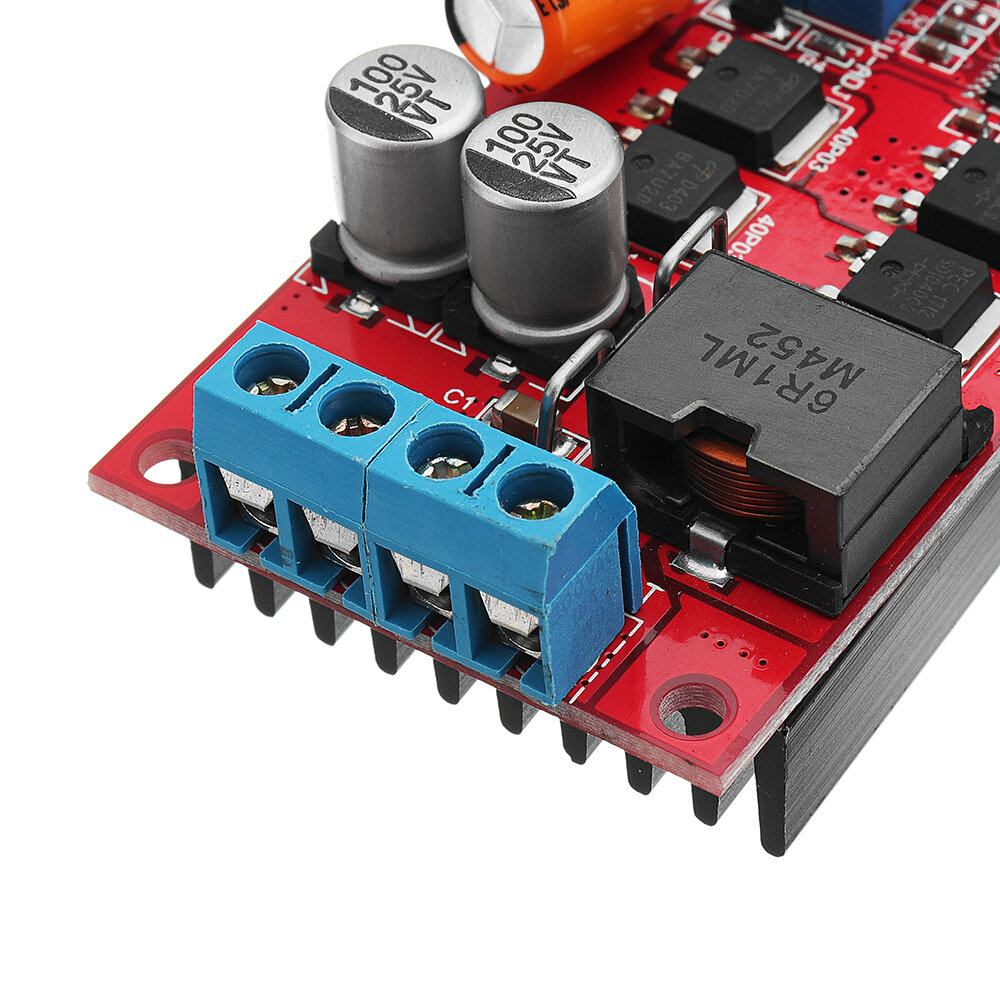
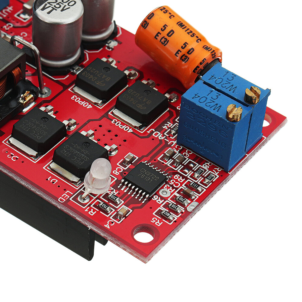
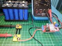
Good product, but cannot deliver charging current of 5A, unless there is proper heatsink on the two diodes and the two mosfets. This may also be due to RCS being bigger than 0.04Ω. In any case the existing heatsink is not correctly glued underneath the components, as it touches only partially some of the heated parts. Even worse, the metal heatsink touches the pins of some other components and there is danger of shorts and damage. Furthermore, in my unit, the dual led is soldered the other way around, and as a result, when it charges a battery, the blue led is on, and when the battery gets full, the red led comes on. Nevertheless, it is a good mppt charger. I attach the Charging Profile and its Diagram, taken from CN3722 datasheet.


This device works quite well at lower currents (< 3A). MPPT via panel voltage tracking seems to work quite well. I have mine outputting an almost consistant 10 Watts(2.8A @ 3.6v) into a 1s20p Lithium battery(nom. 3.6v, 45Ah) from a 12.5 Watt panel (21Voc, 17Vmp), so approx. 80% efficiency, even in 42 degree celcius ambient heat with panel temperature above 60 deg C !! (Australian summer). In 'cooler' summer weather (mid 20's) I get maybe an extra Watt out at mid day (~11W -ish).
Although this is advertised as working up to 5A, even after extensive testing I was not able to get much above 4A with a 25Watt(measured) panel and very good heatsinking: I only get 15 Watts out (4.2A@3.6v) so efficiency at higher currents suffers badly (25W in, 15W out = ~60% efficiency)
This item, as shipped, will NOT work with 1S lithium because the regulation voltage can only be adjusted down to ~6.5v, however, it is relatively easy to modify it for 1S operation. To do this, simply replace the 22k resistor (R7, marked 223, 0603 size) with something around 75k to 100k. I used an 82k resistor which alows me to adjust regulation from ~3.0v to ~9v.
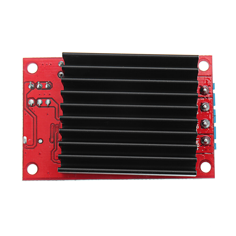
Note that the supplied heatsink itself is okay, but it is useless as supplied because it is mounted with a thick dob of silicone adhesive. This is because A) the current sense shunt resistor is thru-hole and protrudes, and B) the PCB tracks under it have exposed solder pads. Poor design/lack of forethought by whoever did the PCB layout!. Therefore, mounting the heatsink directly to the PCB would cause a short circuit. I have modified mine with heatsinks on the top side packages(Mosfets and Diodes), and also a heatsink with a drilled hole (to clear the shunt solder pad) un the underside using double-sided tape as insulation to avoid shorts with the board tracks. Not exactly ideal, but much better than as-supplied.
Tips:For questions about your order, place of delivery, product discount, taxation, delivery time, warranty, shipping, payment, exchange rate, and other questions unrelated to the product, please contact customer service.
A part of the QA has been auto-translated.
To get the latest brand news and 15% off for your first order.

Hi ?
How can we help?


