


 Direct purchase from the factory

![[US DIRECT] ATOMSTACK A5 M50 APP Control Dual-Laser Laser Engraving Cutting Machine Laser Engraver Cutter 5.5W Output Power Fixed-Focus 304 Mirror Stainless Steel Engraving DIY Laser Marking for Metal Wood Leather Vinyl](https://static.roymall.com/d/file/mall/titlepic/235/67803406-41f3-499a-afb7-154990584ff8.jpg?x-oss-process=image/resize,w_237/quality,Q_80/format,webp)


![[EU/US Direct]Raiser for LONGER RAY5 Engraver](https://static.roymall.com/d/file/mall/bigpic/235/65e9b76d-574a-4b4b-9c6c-02db18b89460.jpg?x-oss-process=image/resize,w_237/quality,Q_80/format,webp)
![[US/UK Direct] Refurbished ULTIMEA Nova S70 3.1.2 Soundbar 390W True Dolby Atmos Soundbar BassMax 4K Dolby Vision HDR Passthrough 3EQ Modes Wired Speaker Subwoofer](https://static.roymall.com/d/file/mall/titlepic/235/e1440062-c78c-4565-8aa7-f8857d749771.jpg?x-oss-process=image/resize,w_237/quality,Q_80/format,webp)


1.You can contact the customer service. for any question regarding the product.
2.Ask the question in English to get answer faster.
3.Keep your question short and to the point.
Questions:0/2000

 Multi Rotor PartsFPV SystemRadios & ReceiverBattery & ChargerTools & Bags & StorageConnector & Cable & WireRC ServosElectronic Learning ToysPlane & Parachute ToysSolar Powered ToysPottery Clay & ToolsPaper Art & DrawingBlocks & Track ToysModel BuildingDiecasts & Model ToysProtective GearsMotorcycle LightsCharger & Socket AdapterMotorcycle Engines & ComponentMotorcycle HelmetMotorcycle DIY KitsMotorcycle AccessoriesMotorcycle Alarm & SecurityCar Stickers & DecalsCar CoversWindow FoilsCar Protective FilmCar Protective Film Body ArmorLicense Plate AccessoriesDIY Electronic KitsElectronic Accessories & SuppliesModule ComponentsBoard & ShieldExpansion Board & ShieldSmart ModuleSensor & Detector ModulePower Supply ModuleRaspberry Pi & Orange PiSecurity Alarm SystemSmart Remote ControlWeather Station & ThermometerAccess Control & IntercomsHome Automatic KitsAutomation ModulesClocksHome Decor StickerDecorative PaintingDecorative CraftsStorage BagsStorage BoxesItems Storage & OrganizationSeedsWatering & IrrigationGarden LightsPest Control ProductsBathroom ApplianceShowerhead & AccessoriesBathroom Storage & OrganisationBathroom SafetyDoor Hardware & LocksIndustrial HardwareDecorative HardwarePackaging & ShippingStorage & OrganizationFurniture HardwareKitchen Tools & GadgetsDrinkware & Tea SetsBakeware & AccessoriesHome Brewing & Wine MakingKitchen Knife & CutleryBarbecue & Picnic SuppliesDinnerware & FlatwareXiaomi Kitchen Appliance
Guaranteed Safe Checkout

 Free Gift
 Shipping Policy
 Return Policy
A part of the review has been auto-translated.

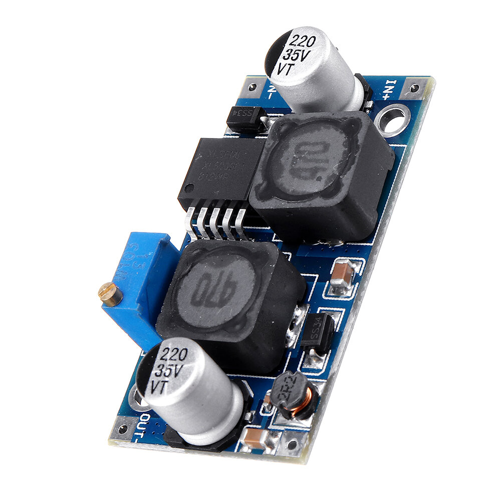
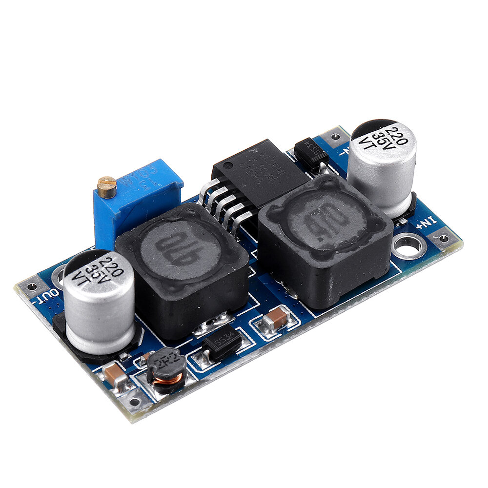
Works as specified if you stay in the limits.
Just a little warning: during my tests, I lowered the input voltage and under 3.5V, the circuit doesn't cut but becomes crazy and the output (that was set to 15V with the pot.) jumps to 40V with no load. With a 2k resistor at the output, it only goes to 30V.
Of course, this is under the specified minimum voltage, but for solar applications, how can you guarantee that the input voltage will not be there?
So when it says "Module Suitable For Solar Panel" I'm suspicious. If you really want to use it like that, you could add a small circuit between the solar panels and the converter to cut it if the voltage drops under the minimum 3.8V or clamp the output with a zener (there's no voltage rating on the output capacitor so that kind of overvoltage could damage it if it is not designed to handle 40V)
Also the problem with that kind of circuit is that if you try to extract too much current from a solar cell, its voltage drops, but then the converter will try to get even more current to keep it's output and the input voltage drops even more... So you also have to add a circuit that limits the output current when the input voltage drops.
Conclusion: good circuit if you use it properly but not really appropriate for solar panels despite what it says in the title.
Will bu used in the future with old PC-power-supplies for variable voltages.
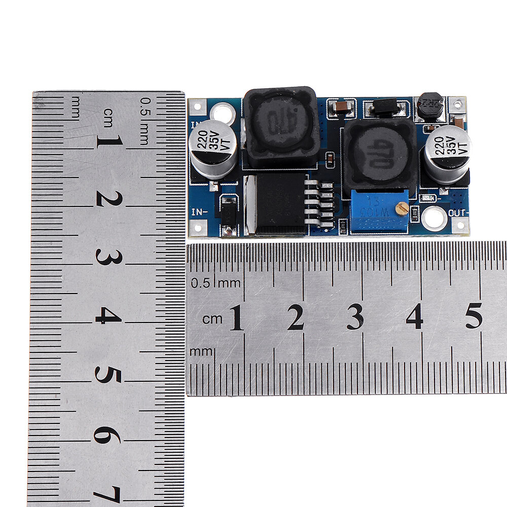
I have tested it with a power supply and measured the output voltage. The input was 7.2 Volts. I have used output at voltages of more than 25 V down to 1.5 Volts.
The trimmer for the output voltage is extremely sensitive (10 turn potentiometer) so that the exact voltage can be set easily.
The input voltage should be 5 Volt or higher for stable output.


Tips:For questions about your order, place of delivery, product discount, taxation, delivery time, warranty, shipping, payment, exchange rate, and other questions unrelated to the product, please contact customer service.
A part of the QA has been auto-translated.
To get the latest brand news and 15% off for your first order.

Hi ?
How can we help?


